X-ray Image Intensifiers
Medical
Below information is purpose for of development, design and production of medical device systems by implementing our company's products. Technical and regulatory confirmation/verification is necessary before purchasing and using of these products.
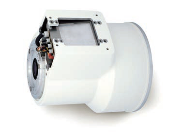
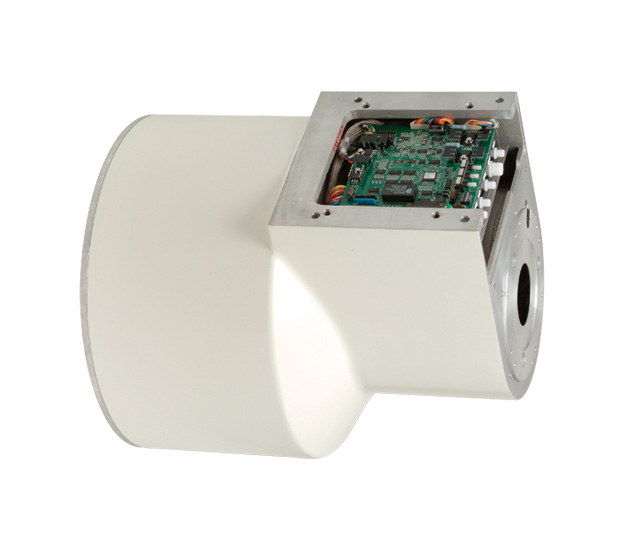
The input window of the image intensifier(I.I.) is vapor-deposited with a thick film of extremely fine pillar crystal phosphor, which reduces light diffusion and improves X-ray conversion efficiency.
Lineup
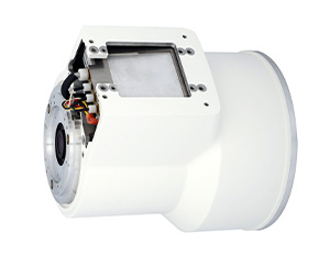
4-inch
Click photo to enlarge.
| Image | Model Name | Nominal Entrance Field Size |
Useful Entrance Field Size |
Output Image Dia- meter (mm) |
Central Resolution (Lp/cm) typical |
Contrast Ratio typical |
DQE (IEC Stan- dard) |
Mechanical | Appli- cation |
Download | ||||
|---|---|---|---|---|---|---|---|---|---|---|---|---|---|---|
| Normal mode |
Normal mode |
M mode |
Nor- mal mode |
M mode |
10% area | 10 mm dia. |
typical | Overall length | Mounting Surface | |||||
|
E5877J -P1 |
100 mm min. |
95 mm min. | 50 ±5 mm | 20 ±1 | 77 | 110 | 22:1 | 18:1 | 42% | 226 ±3 mm |
Side of the image intensifier |
C-arm/ Fluoro table |
- |
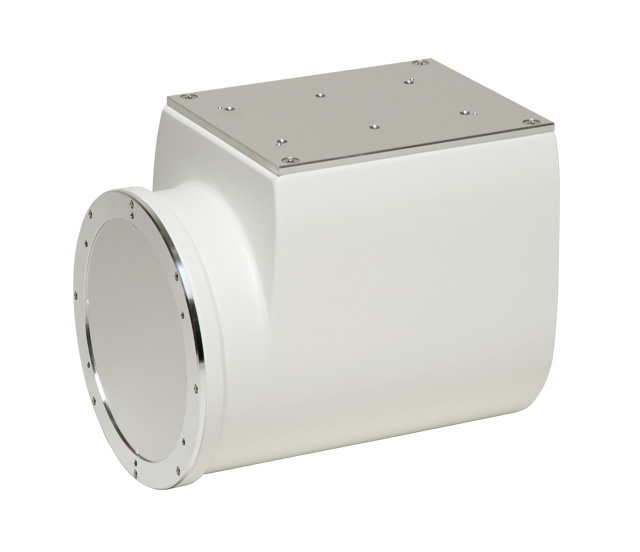
6-inch
Click photo to enlarge.
| Image | Model Name | Nominal Entrance Field Size |
Useful Entrance Field Size |
Output Image Dia- meter (mm) |
Central Resolution (Lp/cm) typical |
Contrast Ratio typical |
DQE (IEC Stan- dard) |
Mechanical | Appli- cation |
Download | ||||
|---|---|---|---|---|---|---|---|---|---|---|---|---|---|---|
| Normal mode |
Normal mode |
M mode |
Nor- mal mode |
M mode |
10% area | 10 mm dia. |
typical | Overall length | Mounting Surface | |||||
|
E5870SD -P6A |
150 mm min. |
140 mm min. | 105 ±5 mm | 20 ±0.5 | 66 | 77 | 30:1 | 20:1 | 42% | 276 ±5 mm | Side of the image intensifier & Front of the image intensifier | MiniC-arm/CBCT | - |
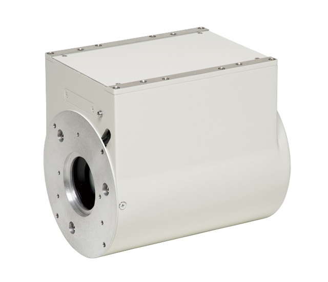
9-inch
Click photo to enlarge.
| Image | Model Name |
Nominal Entrance Field Size | Useful Entrance Field Size |
Output Image Dia- meter (mm) |
Central Resolution (Lp/cm) typical |
Contrast Ratio typical |
DQE (IEC Stan- dard) |
Mechanical | Appli- cation |
Download | ||||||
|---|---|---|---|---|---|---|---|---|---|---|---|---|---|---|---|---|
| Normal mode |
Normal mode |
M1 mode |
M2 mode |
Nor- mal mode |
M1 mode |
M2 mode |
10% area | 10 mm dia. | typical | Overall length | Mounting Surface | |||||
|
E5764SD -P4A |
230 mm min. | 215 mm min. | 160 ±5 mm | 120 ±5 mm | 20 ±0.5 | 48 | 56 | 66 | 25:1 | 16:1 | 65% | 338 ±5 mm |
Same side as the power supply box & Front of the image intensifier | C-arm/ Fluoro table |
- |
| E5830SD -P4A |
25 ±0.5 | 52 | 58 | 68 | 30:1 | 19:1 |
(291KB) |
|||||||||
|
E5764SD -P7A |
20 ±0.5 | 48 | 56 | 66 | 25:1 | 16:1 | 341 ±5 mm | Same side as the power supply box | C-arm |
(705KB) |
|||||
| E5830SD -P7A |
25 ±0.5 | 52 | 58 | 68 | 30:1 | 19:1 |
(705KB) |
|||||||||
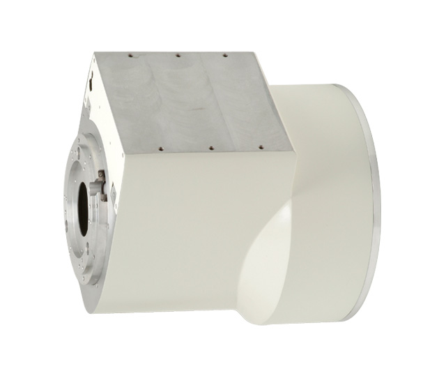
12-inch
Click photo to enlarge.
| Image | Model Name |
Nominal Entrance Field Size | Useful Entrance Field Size |
Output Image Dia- meter (mm) |
Central Resolution (Lp/cm) typical |
Contrast Ratio typical |
DQE (IEC Stan- dard) |
Mechanical | Appli- cation |
Download | ||||||
|---|---|---|---|---|---|---|---|---|---|---|---|---|---|---|---|---|
| Normal mode |
Normal mode |
M1 mode |
M2 mode |
Nor- mal mode |
M1 mode |
M2 mode |
10% area | 10 mm dia. |
typical | Overall length | Mounting Surface | |||||
|
E5765SD -P2A |
310 mm min. |
290 mm min. | 215 ±5 mm | 160 ±5 mm | 25 ±0.5 | 46 | 50 | 56 | 24:1 | 15:1 | 65% | 434.5 ±5 mm |
Side of the image intensifier & Front of the image intensifier |
C-arm/ Fluoro table |
- |
| E5796SD -P2A |
30:1 | 18:1 |
(275KB) |
|||||||||||||
The product information shown in the lineup table is not intended as an advertisement or inducement for the Japanese domestic market.
Inquiry About Products
USA:+1-800-970-7227
Europe:+31-20-399-9087
Japan:+81-44-739-6502
China(Shanghai):+86-21-6361-0077
China(Beijing):+86-10-8525-8277