For Industrial
For In-line Testing System
Below information is purpose for of development, design and production of industrial inspection systems
by implementing our company's products.
Technical and regulatory confirmation/verification is necessary before purchasing and using of these
products.
Lineup
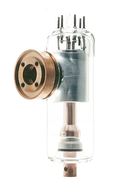
Industrial X-ray Tubes
Click photo to enlarge.
| Image | Model Name | Target Material |
Focal Spot (mm) |
Max. Rating (W) |
Max. Voltage (kV) |
Max. Current (mA) |
Circuit | Ground | Target Angle (°) |
Be Thickness (mm) |
Dimensions Length x Diameter (mm) |
Appli cation |
Down load |
|---|---|---|---|---|---|---|---|---|---|---|---|---|---|
| - | I-2118B | W | 1×0.7 | 55 | 55 | 1 | C | N | 20 | Glass1.7 | 96×30.5 | F |
(157KB) |
| - | E7690 | W | 1×1 | 350 | 75 | 8 | C | CG | 20 | 1 | 185×62 | F |
(225KB) |
 |
I-2112B | Rh | 0.8 | 50 | 50 | 1 | C | CG | 33 | 0.05 | 96×33 | A |
(182KB) |
|
I-2113A | Mo | 0.15 | 75 | 50 | 1.5 | C | CG | 10 | 0.05 | 96×33 | A,T |
(163KB) |
|
I-2115C | W,Mo | 0.15 | 75 | 50 | 1.5 | C | CG | 10 | 0.2 | 96×33 | A,T | - |
 |
I-2122A | W | 0.15x0.1 | 50 | 50 | 1 | C | CG | 16 | 0.2 | 96×30.5 | A,T |
(172KB) |
|
I-2123 | W | 0.1 | 50 | 60 | 1.2 | C | CG | 10 | 0.2 | 96×30.5 | N |
(166KB) |
| - | I-317 | W | 0.1 | 50 | 100 | 0.83 | C | CG | 10 | 0.5 | 180×62 | N |
(170KB) |
- Notes
- Circuit : C=DC1, S=self-rectification
Ground : AG=Anode ground, CG=Cathode ground
Application : T=Thicknessmeter, A=Analysis, N=Nondestructive
* : Input peak power (1 pluse)
X-ray Image Intensifiers
4-inch
Click photo to enlarge.
| Image | Model Name | Material of Input Window |
Application | Central Resolution | Contrast Ratio | ||
|---|---|---|---|---|---|---|---|
| Normal mode (Lp/cm typ.) |
Magnified mode (Lp/cm typ.) |
10% area (typ.) |
10 mm dia. (typ.) |
||||

|
E5877J-P1AK | Al (Aluminium) |
Standard | 4" mode: 77 | 2" mode: 110 | 22:1 | 18:1 |
| E5877K-P1K | High-Resolution | 4" mode: 92 | 2" mode: 125 | 26:1 | 19:1 | ||
| E5877RE-P1K | High-Speed Response | 4" mode: 77 | 2" mode: 110 | 22:1 | 18:1 | ||
| E5889BE-P1K | Be (Beryllium) |
Standard | 4" mode: 77 | 2" mode: 110 | 22:1 | 18:1 | |
| E5889K-P1K | High-Resolution | 4" mode: 92 | 2" mode: 125 | 26:1 | 19:1 | ||
| E5889BP-P1K | High-Speed Response | 4" mode: 77 | 2" mode: 110 | 22:1 | 18:1 | ||
6-inch
Click photo to enlarge.
| Image | Model Name | Material of Input Window |
Application | Central Resolution | Contrast Ratio | ||
|---|---|---|---|---|---|---|---|
| Normal mode (Lp/cm typ.) |
Magnified mode (Lp/cm typ.) |
10% area (typ.) |
10 mm dia. (typ.) |
||||

|
E5870SD-P6AK | Al (Aluminium) |
High-Resolution | 6" mode: 66 | 4" mode: 77 | 30:1 | 20:1 |
Radiation Detectors
Ionization Chambers
| General Specifications | Window Specifications | Electrical Specifications | ||||||||||||
| Image | Tube Type | Fill Gas | Housing Material | Gas Pressure | Length | Diameter | Effective Length | Operating Tempe- rature |
Material | Thick- ness |
Dimen- tion |
Operating Voltage Range | Maximum Voltage | Down load |
|---|---|---|---|---|---|---|---|---|---|---|---|---|---|---|
| - | E6854 | 100 %Xe |
SGP | approx. 0.8MPa | 209 mm |
113 mm |
150 mm |
-20°C ∼ 70°C |
Beryllium | 2.0 mm |
Φ70 mm |
200 - 700VDC |
1500 VDC |
- |
| - | E6861 | Al | approx. 0.8MPa | 220 mm |
50 mm |
167 mm |
- | 1.0 mm |
- | 300 - 700VDC |
- | |||
| - | E6866A | SUS304 | approx. 1.5MPa | 174.5 mm |
15 mm |
100 mm |
-20°C - 70°C |
- | 0.5 mm |
- | 300 - 700VDC |
- | ||
| - | E6866C | approx. 3.0MPa | - | |||||||||||
| - | M4952F | SGP | approx. 0.4MPa | 220 mm |
140 mm |
50 mm |
SUS304 | 0.5 mm |
Φ132 mm |
100 - 300VDC |
- | |||
Inquiry About Products
USA:+1-800-970-7227
Europe:+31-20-399-9087
Japan:+81-44-739-6502
China(Shanghai):+86-21-6361-0077
China(Beijing):+86-10-8525-8277